Specification for James Hargreaves’ Spinning Jenny, 1764 (C210/11)
This was a multi-spindle spinning machine. It meant that a spinner could produce more yarn at a time of increased demand from weavers involved in the manufacture of cloth.
Transcript
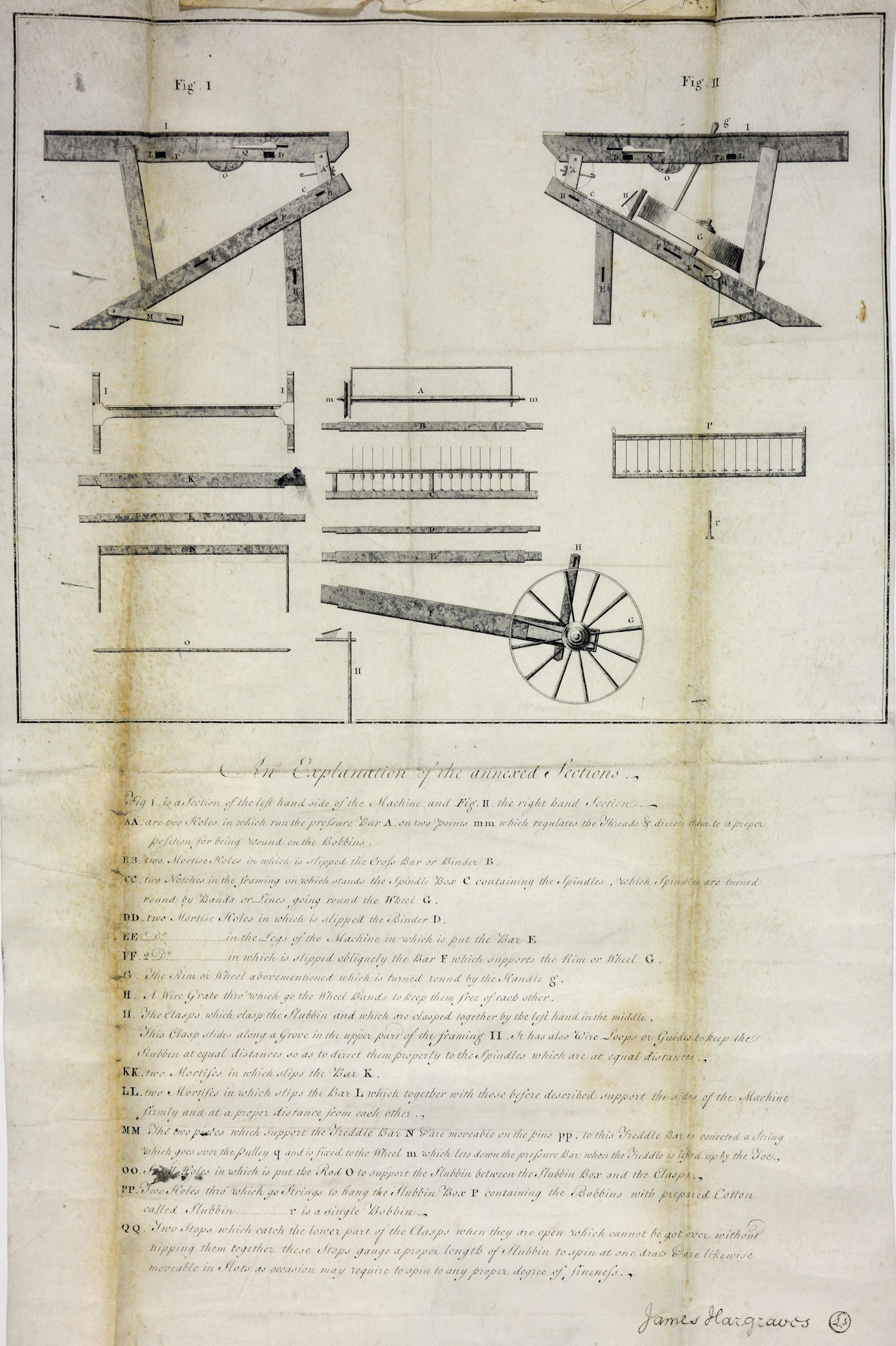
An Explanation of the Annexed Sections
Fig. I. is a section of the left hand side of the Machine and Fig. II is the right hand Section.
- A. are two Holes in which run the pressure Bar A. on two points mm which regulates the Threads & directs them to a proper position for being wound on Bobbins.
- B. two Mortise Holes in which is slipped the Cross Bar or Binder B
- two Notches in the framing on which stands the Spindle Box C containing the Spindles which spindles are turned round by Bands or Lines going round Wheel G
- two Mortise Holes in which is slipped the Binder D
- Ditto in the Legs of the Machine is put the Bar E
- Ditto in which is slipped obliquely the Bar F which supports the Rim or Wheel G
- The Rim or Wheel above mentioned which is turned round by the handle g
- A wire Grate through which go the Wheel Bands to keep them free of each other
- The clasps which clasp the slubbin [short fibres to be spun into thread] and which are clasped together by the left hand in the middle. This clasp slides along a Groove in the upper part of the framing II. It has also Wire Loops or Guides to keep the Slubbin at equal distances so as to direct them properly to the Spindles which are at equal distances.
- K. two Mortises in which slips the Bar K
- L. two Mortises in which slips the Bar L which together with those before
described support the sides of the Machine firmly and at a proper distance
from each other.
- M. The two pieces which support the Treddle Bar N are moveable on the
pins pp, to this Treddle Bar is connected a String which goes over the
pulley q and is fixed to the Wheel m which lets down the pressure Bar
when the Treddle is lifted up by the Toe.
- O. [word unclear] Holes in which is put the Rod O to support the Slubbin
between The Slubbin Box and the Clasps.
- P. The two holes through which go strings to hang the slubbin Box P
containing the bobbins with prepared Cotton called Slubbin___r is a single
bobbin.
- Q. Two stops which catch the lower part of the Clasps when they are open
Cannot be got over without nipping them together, these stops gauge a
Proper length of slubbin to spin at one draw and are likewise
moveable in slots as occasion may require to spin any proper degree of
fineness.
James Hargraves